Thermal Design and Cooling Solutions for New Energy Inverters Explained
Explore expert thermal design of new energy inverters with a detailed comparison of cooling solutions for efficiency and reliability.
Heat Generation Mechanisms in New Energy Inverters
Understanding heat generation in new energy inverters is critical for effective thermal design. The primary sources of heat come from power semiconductors and passive components, each contributing differently to the overall thermal load.
Switching and Conduction Losses in Power Semiconductors
- IGBTs vs. SiC/GaN MOSFETs: Traditional IGBTs exhibit higher conduction and switching losses compared to wide bandgap (WBG) devices like SiC and GaN MOSFETs. WBG devices operate at higher switching frequencies with lower losses but generate heat predominantly through switching transitions.
- High Switching Frequencies: Increasing switching frequencies enhances inverter efficiency but raises switching losses, causing elevated junction temperatures. Managing these thermal spikes is vital to maintaining device reliability and performance.
Heat from Passive Components
- DC-Link Capacitors: These components are sensitive to temperature; losses and dielectric heating increase with heat, reducing lifespan.
- Busbars and Inductors: Resistive losses in busbars and core losses in inductors and magnetic components generate additional heat.
- Magnetics: Core and winding losses in transformers contribute to the thermal load, often overlooked but significant in high-power applications.
Environmental and Operational Influences
- Ambient Conditions: Higher ambient temperatures directly increase cooling requirements and stress on the inverter.
- Load Profiles: Variable and peak loads create fluctuating thermal demands, requiring robust design to handle transient heat spikes.
- System Integration: Compact, integrated inverter designs often face tighter thermal constraints compared to discrete assemblies, influencing heat dissipation strategies.
By grasping these heat generation mechanisms—switching losses, conduction losses, and contributions from passive parts—engineers can better address thermal management challenges in EV inverters, photovoltaic systems, and energy storage solutions. Focusing on these factors helps optimize thermal solutions for reliability and efficiency.
Key Components Requiring Focused Thermal Design
Thermal management in new energy inverters demands special attention to several key components prone to heat stress. First are the power semiconductor modules, including IGBTs and SiC MOSFET dies, along with their substrates and baseplates. These components generate significant heat during switching and conduction, especially under high power loads. For example, advanced modules like the 1200V-75mΩ silicon carbide power MOSFET offer improved thermal performance but still require optimized heat dissipation paths.
DC-link capacitors are another critical focus area because their lifespan and performance decline rapidly with temperature rises. Maintaining capacitor temperatures within safe limits prevents premature failure and ensures stable power filtering.
Magnetic components such as inductors and transformers contribute to the overall thermal load through core and winding losses. Efficient design minimizes heat buildup in these parts, crucial for reliable operation, especially in compact inverter designs.
Beyond power devices and passives, control boards, drivers, and auxiliary circuits also need protection from thermal extremes to guarantee long-term stability and precise control functions.
Finally, thermal bottlenecks often appear in the integration choice: integrated designs pack components densely, which can create hotspots, whereas discrete assemblies allow more optimized cooling but at the cost of size and complexity. Balancing these factors is key to effective inverter thermal design tailored to specific application needs like EVs or photovoltaic systems.
Core Principles of Thermal Design for Inverters
Effective inverter thermal design hinges on understanding and managing the thermal resistance network—this includes junction-to-case, case-to-sink, and sink-to-ambient paths. Each step in this chain plays a crucial role in how heat travels away from power semiconductor devices like IGBTs and SiC MOSFETs, directly impacting reliability and performance.
For wide bandgap (WBG) devices such as SiC and GaN, junction temperature limits typically range from 150°C up to 200°C. Staying within these limits is vital because exceeding them accelerates device aging and can cause premature failures, making thermal management a top design priority.
Modern thermal design also leans heavily on simulation tools like Computational Fluid Dynamics (CFD) and Finite Element Analysis (FEA). These allow engineers to predict temperature distributions, identify hotspots, and optimize cooling arrangements before physical prototypes are built.
Material choice is another cornerstone. Substrates such as Direct Bonded Copper (DBC) and Aluminum Nitride (AlN) ceramics are favored for their excellent thermal conductivity. Baseplates and Thermal Interface Materials (TIMs) are also selected to minimize thermal resistance and ensure efficient heat transfer from semiconductor modules to heatsinks or cooling plates.
To reduce thermal gradients and prevent hotspots, designers implement strategies including uniform heat spreading, proper mounting pressure for TIMs, and optimized component layout. This holistic approach is critical to maximizing inverter efficiency and lifespan, especially in high-power applications like electric vehicles (EVs) and renewable energy systems.
For robust solutions, power modules such as the high-voltage IGBT modules available through providers like Hiitio Semiconductor exemplify components designed with these thermal principles in mind, combining advanced materials and construction.
Overview of Cooling Solutions for New Energy Inverters
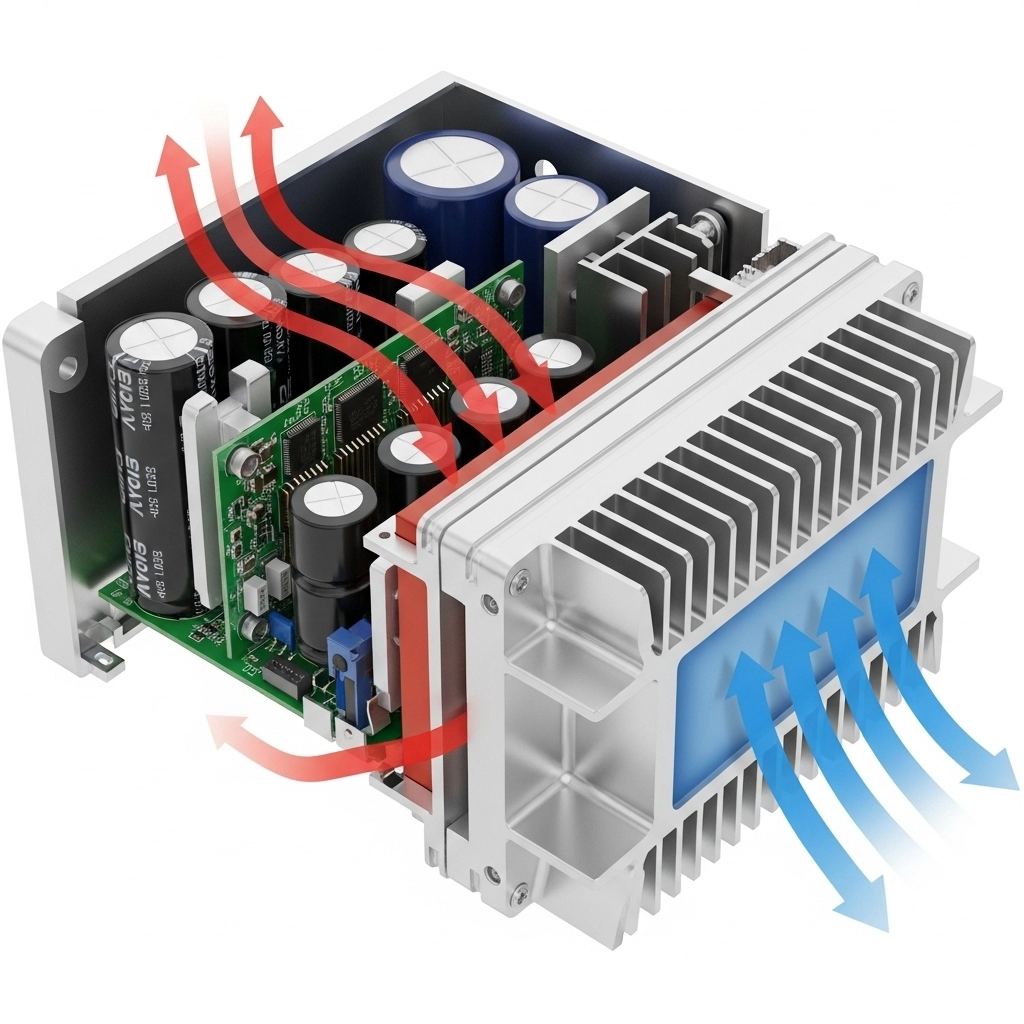
When it comes to inverter thermal management, cooling solutions generally fall into three main categories: passive, active, and advanced/hybrid cooling. Passive cooling relies on natural convection and radiation, offering simplicity and zero maintenance but limited heat removal capacity. Active cooling, like forced air or liquid cooling, uses fans or pumps to move heat away quickly, making it suitable for higher power density applications. Advanced or hybrid methods blend these approaches, incorporating technologies such as heat pipes, phase change materials, or immersion cooling for improved efficiency where space and performance demand it.
Choosing the right cooling solution depends on several factors:
- Power level and heat flux: Higher power inverters generate more heat, often pushing toward liquid or hybrid cooling.
- Space constraints: Compact designs benefit from cooling methods that provide high heat removal without bulky components.
- Cost and maintenance: Passive cooling saves costs upfront and during operation, while active and hybrid solutions may require more investment and upkeep.
- Noise: Fan noise from forced air cooling can be a concern in residential or office environments.
- Reliability and longevity: Cooling solutions must align with the expected lifetime and operating conditions of the inverter, balancing complexity with performance.
Whether it’s an EV inverter needing robust heat dissipation or a photovoltaic inverter where space and noise are critical, weighing these factors helps in selecting the best power electronics cooling strategy to maximize efficiency and device lifespan. For example, advanced SiC modules like the ED3 1200V 600A SiC power module offer opportunities to push cooling performance while managing thermal loads effectively.
Detailed Comparison of Major Cooling Solutions for New Energy Inverters
Choosing the right cooling method for inverter thermal management is key to ensuring performance, reliability, and cost-effectiveness. Here’s a straightforward look at the main cooling solutions used in new energy inverters, with their main pros, cons, and typical applications.
| Cooling Type | Advantages | Limitations | Typical Applications |
|---|---|---|---|
| Natural Convection Air Cooling | No moving parts, low cost, silent | Limited heat dissipation, requires good airflow | Low-power PV inverters, small ESS systems |
| Forced Air Cooling (Fans + Heat Sinks) | Better heat removal, flexible design | Noise, dust buildup, additional maintenance | Medium-power EV inverters, industrial drives |
| Liquid Cooling (Water-Glycol / Dielectric Fluids) | High heat flux removal, compact design | Complex system, cost, potential leaks | High-power EV inverters, large ESS and PV plants |
| Advanced & Hybrid Cooling (Heat Pipes, PCM, Immersion) | Very efficient hotspot control, potential for compactness | Emerging tech, cost, integration challenges | Cutting-edge EV inverters, high-density power modules |
Natural Convection Air Cooling
This is the simplest cooling approach relying on airflow without fans. Its silent operation and low cost make it ideal for small-scale applications. However, it struggles with higher power densities due to limited heat transfer capabilities.
Forced Air Cooling (Fans + Heat Sinks)
Adding fans to heat sinks forces airflow, improving heat dissipation significantly. Design must consider fan reliability and noise, plus dust and maintenance issues. This method suits medium-power applications like many IGBT power modules in electric vehicles and industrial gear.
Liquid Cooling (Water-Glycol / Dielectric Fluids)
Liquid cooling uses cold plates in contact with power semiconductors (like SiC MOSFETs) to achieve superior heat removal. It supports higher power densities while keeping junction temperatures in check. Complexity, cost, and risk of coolant leaks are downsides. This solution fits high-power EV inverter setups and large-scale energy storage systems.
Advanced and Hybrid Cooling Techniques
Techniques like heat pipes, vapor chambers, phase change materials (PCM), and immersion cooling are gaining traction for their ability to manage hotspots efficiently. Though expensive and complex, they enable compact, high-performance inverter designs especially with WBG semiconductor modules. These solutions are often seen in research and premium EV inverter products.
By comparing thermal performance, efficiency gains, cost, and reliability:
| Cooling Type | Thermal Performance | Efficiency Impact | Cost | Complexity | Reliability |
|---|---|---|---|---|---|
| Natural Convection | Low | Minimal | Low | Low | High |
| Forced Air Cooling | Moderate | Moderate | Moderate | Moderate | Moderate |
| Liquid Cooling | High | High | High | High | Moderate-High |
| Advanced/Hybrid Cooling | Very High | Very High | Very High | High | Emerging |
This side-by-side helps weigh the trade-offs based on your inverter’s power rating, space, and operational priorities.
For solid inverter thermal design, evaluating these cooling options through the lens of your specific application—be it EV, photovoltaic (PV), or energy storage—is crucial for optimal heat dissipation and long-term reliability. For example, pairing efficient SiC MOSFET modules with an effective liquid cooling system can drastically improve heat dissipation and inverter performance.
Performance Metrics and Trade-Off Analysis
When evaluating inverter thermal management solutions, it’s key to weigh performance against costs and reliability. Here’s a quick breakdown of the main factors:
Temperature Reduction & Power Density
- Effective cooling lowers junction temperatures, directly boosting power density and efficiency.
- For instance, liquid cooling systems can drop temperatures 20–30°C more than forced air, enabling higher current loads without thermal derating.
- This translates to smaller, lighter inverter designs, especially critical in EV inverters and high-power photovoltaic (PV) systems.
Efficiency Improvements
- Cooler semiconductor junctions reduce conduction and switching losses, improving inverter efficiency by up to 1-2%.
- Efficient heat removal also stabilizes performance under varying load profiles, maintaining consistent operation.
Reliability Impact
- Lifetime predictions rely heavily on thermal data using Arrhenius models. Every 10°C drop in junction temperature can roughly double the device lifetime.
- For example, power modules like the Econo Dual 3H 1200V 600A IGBT benefit from precise thermal management to maximize durability in harsh conditions.
Cost vs. Benefit Analysis
- Forced air cooling keeps upfront costs low but offers limited performance at high heat fluxes.
- Liquid cooling and hybrid systems require higher initial investment but deliver better long-term ROI through energy savings and reduced failure risks.
- Application matters: EV inverters prioritize compactness and efficiency, favoring liquid cooling. PV installations often balance cost and maintenance by using air or hybrid cooling solutions, while energy storage systems (ESS) sometimes opt for advanced cooling to handle consistent loads.
Environmental Considerations
- The energy consumed by cooling systems adds to operational expenses and carbon footprint.
- Passive and hybrid designs can reduce energy use versus traditional active cooling without sacrificing performance.
- Sustainable coolants and AI-optimized thermal management increasingly support greener inverter solutions.
Balancing these metrics is crucial for designing robust and efficient new energy inverters tailored to US customers’ diverse needs, whether for automotive, renewable energy, or large-scale storage applications.
Best Practices and Emerging Trends in Inverter Thermal Design
Choosing the right cooling solution for new energy inverters depends heavily on the specific application. Electric vehicles (EVs), photovoltaic (PV) systems, and energy storage solutions (ESS) all have different power levels, space constraints, and thermal demands. For example, high-power EV inverters often benefit from liquid cooling or hybrid cooling systems to handle dense heat flux, while smaller PV inverters may rely on efficient forced air cooling to balance cost and performance.
Advanced materials are key to pushing thermal management limits. Aluminum Nitride (AlN) ceramics provide excellent thermal conductivity for substrates, helping lower thermal resistance between power semiconductor dies and heat sinks. High-performance thermal interface materials (TIMs)—including phase change materials (PCMs)—reduce thermal bottlenecks by improving heat transfer, especially at interfaces where uneven surfaces can cause hotspots.
Integration trends are also shaping thermal design. Oil-cooled unified systems combine power electronics and cooling fluid in a compact setup, enhancing both reliability and space utilization. With wide bandgap (WBG) devices like SiC MOSFETs now operating at higher junction temperatures, the thermal design focus shifts toward accommodating those conditions without sacrificing lifespan.
Looking ahead, AI-optimized thermal designs will become more common, allowing real-time adjustments and predictive maintenance based on operational data. Sustainable coolants—such as biodegradable dielectric fluids—are emerging to reduce environmental impact while maintaining excellent heat removal.
By mixing these strategies—application-driven cooling selection, advanced materials, system integration, and smart technologies—you can achieve reliable, efficient thermal management tailored for the evolving demands of new energy inverters.