Selection of SiC MOSFET for Inverter Welding Applications
Explore the SiC high-frequency inverter welding machine schematic, working principle, topology structure, and expert SiC MOSFET and diode selection for 10–30kW systems.
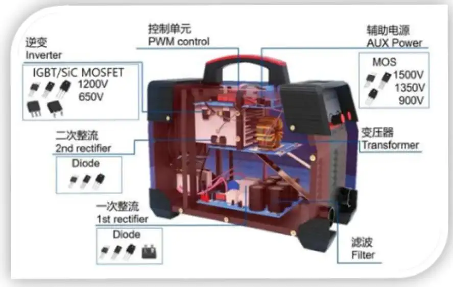
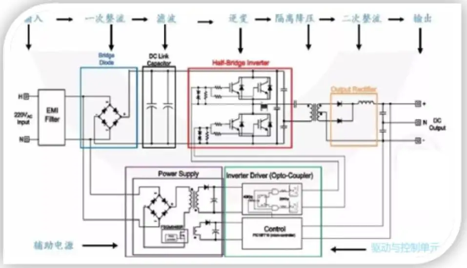
Overall schematic diagram of SiC high-frequency inverter welding machine
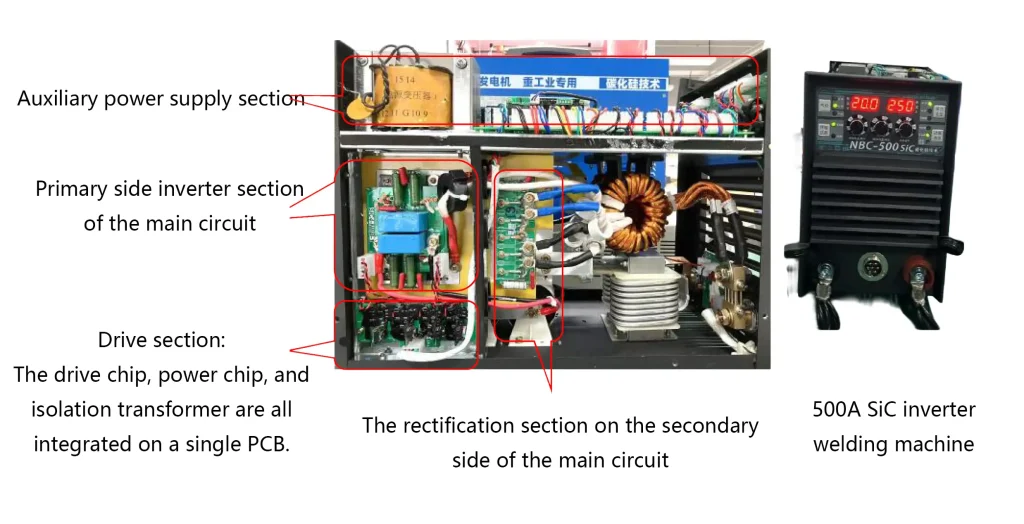
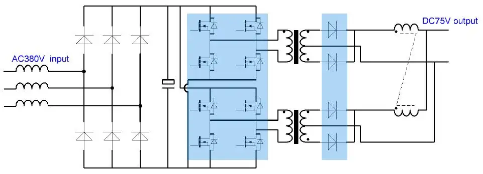
The working principle and topology structure of the inverter welding machine
The working process of the inverter welding machine is as follows: alternating current (AC) – direct current (DC) – high-frequency AC – voltage transformation – DC. It first rectifies and filters the three-phase or single-phase AC power to obtain a relatively smooth DC
voltage. Then, the inverter circuit converts this DC voltage into 15 to 100 kHz alternating current. After being stepped down by the medium-frequency main transformer, it is rectified and filtered again to obtain a stable DC output.
Recommendation for the Selection of SiC and Integrated Circuits in Inverter Welding Machines
Welding machine power: 10 – 30 kW
Gas shielded welding, manual welding
| Circuit location | Welding machine outputcurrent | SiC MOSFET discretecomponents | SiC MOSFET module | Isolation driver chip | Power control chip | Sic SBD |
|---|---|---|---|---|---|---|
| Primary side inverter of themain circuit | (250-300)A | HCM39K120Z*8 | / | / | / | |
| (350-500)A | HCM64K120Z*8 | HCS240FH120G3 HCS80FH120A1A3 HCS80FH120A1A3 |
/ | / | / | |
| Above 500A or cutting machine | HCM80K120Z*8 | / | / | / | ||
| Gate drive board | / | / | / | HCD5350MCPR*8 HCD5350MCWR*8 HCD25350MMCWR*4 |
HCP1521DHCP1521S | / |
| Main circuit secondary siderectification | Cutting machine | / | / | / | HCD40D065HC*8 | |
| Auxiliary power supply | / HCM600S170R | / | / | HCP284XR | / | |
Introduction to the Second-Generation SiC MOSFET Discrete Devices
| Voltage | Ros(on) | T0-247-3 | T0-247-4 | TO-247PLUS-4 | TO-263-7 | SOT-227 |
|---|---|---|---|---|---|---|
| 650V | 40mΩ | HCM040K065Z | HCM040J065R | |||
| 750V | 8mΩ | HCM008K075HK | ||||
| 4mΩ | HCM004KP075Y | |||||
| 1200V | 160mΩ | HCM160D120H | HCM160K120Z | HCM160J120R | ||
| 80mΩ | HCM080D120H | HCM080K120Z | HCM080J120R | |||
| 65mΩ | HCM065D120H | HCM065K120Z | HCM065J120R | |||
| 40mΩ | HCM040D120H | HCM040K120Z | HCM040J120R | |||
| 30mΩ | HCM030K120Z | HCM030J120R | HCM030P120N | |||
| 13mΩ | HCM013D120H | HCM013K120Z | ||||
| 11mΩ | HCM011K120HK | HCM012P120N | ||||
| 8mΩ | HCM008KP120Y | |||||
| 6mΩ | HCM004KP120Y | |||||
| 1700V | 600mR | HCM060D170H | HCM060K170Z | HCM600S170R | ||
| 2000V | 24mΩ | HCM024D200H | ||||
| 3300V | 1000mΩ | HCM100J330R |
Introduction to SiC MOSFET Industrial Modules
| Voltage1200V | Packaging type | Product model | Ros(on) | ID |
| HSOP8 | HCM040H120T | 40mR | 40A@Tc=25℃ | |
| HCM080H120T | 80mR | 28A@Tc=25℃ | ||
| Easy 1B | HCS11H120E1G3 | 11mR | 100A@Tc=65℃ | |
| Easy 2B | HCS240PM120E2G3 | 5.5mR | 240A@Tc=65℃ | |
| HCS008H120E2G3 | 8mR | 160A@TC=100℃ | ||
| 34mm | HCS080FH120A1 | 15mR | 80A@TC=100℃ | |
| HCS160FH120A1 | 7.5mR | 160A@Tc=100℃ | ||
| 62mm | HCS300FH120A2 | 3.8mR | 300A@Tc=100℃ | |
| HCS450FH120A2 | 2.5mR | 450A@Tc=100℃ |
Selection of 650V Silicon Carbide Schottky Diodes
| Voltage | Current | T0-220-2 | TO-220F-2 | TO-220-isolated | T0-247-3 | T0-247-2 | T0-252 | T0-263 | SOT-227 |
|---|---|---|---|---|---|---|---|---|---|
| 650V | 4A | HCM004A065K1 | HCM004F065F1 | HCM004C065E1 | |||||
| 6A | HCM006A065K1 | HCM006F065F1 | HCM006C065E1 | ||||||
| 8A | HCM006A065K1 | ||||||||
| 10A | HCM010A065K1 | HCM010F065F1,HCM010F065F | HCM010A065KS | HCM010C065E1,HCM010C065E | HCM010G065F1,HCM010G065F | ||||
| 16A | HCM016D065C1 | HCM016G065F1 | |||||||
| 20A | HCM020A065K1 | HCM020D065C1,HCM020D065C | HCM020H065H1 | ||||||
| 30A | HCM030D065C1 | HCM030H065H1 | |||||||
| 40A | HCM040D065C | HCM040H065H1 | |||||||
| 60A*2 | HCM120P065N1 |